Optimal Actuator Design
In designing a robot, the actuator’s allowable mass and required output torque are determined by the application. However, these requirements still leave a broad design space within which to select motor size and gear ratio. We have developed an actuator design method that enables force control in applications with highly dynamic environmental interactions. The method optimizes the motor selection and gear ratio for high fidelity proprioceptive force control within given actuator weight constraints. We implemented the method in the primary actuators of the MIT Cheetah.
Motivation
The high speed legged locomotion of the MIT Cheetah requires high accelerations and loadings of the robot’s legs. Because of the highly dynamic environmental interactions that come with running, variable impedance of the legs is desirable; however, existing actuation strategies cannot deliver. Typically, electric motors achieve their required torque output and package size through high gear ratios. High ratios limit options for control strategies. For example, closed loop control is limited to relatively slow speed dynamics. Series elastic actuation adds additional actuators and increases system complexity and inertia. We believed a better option existed. In the end, we developed a novel actuator, optimal in many applications.
Goals
The actuator design method seeks to give us the ideal actuator for a given application. In the case of the MIT Cheetah, the ideal actuator has:
- Appropriate torque output. Obviously, the actuator must be able to output the required torque for the application, which can be quite high. For instance, high speed running sees high ground reaction forces, multiple times the weight of the runner.
- High torque density. Torque density, or the continuous output torque per mass, relates the output of the actuator to its size and weight. The higher the torque density the better, since it allows a smaller, lighter, and/or more backdrivable and transparent actuator.
- High Backdrivability. The more backdrivable an actuator, the easier it is to move the end effector and drive the transmission in reverse. High backdrivability protects the system against damage in environmental impacts, especially unexpected ones.
- High Transparency. Transparency describes how easily energy flows between the actuator and end effector in both directions. High transparency allows for energy regeneration to extend battery life and for the use of effective control strategies like open loop impedance control. Note that a highly backdrivable actuator is typically also highly transparent.
- High Efficiency. Efficiency is of course critical in mobile applications – the more efficient the better.
Theory
Dimensional analysis of a typical brushless motor shows us the critical metric: the gap radius, or the distance from the axis of rotation to the center of the gap between rotor and stator.
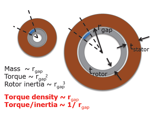
In particular, we see that the output torque scales with the square of the gap radius and the mass with the gap radius, assuming the thicknesses of the rotor and stator remain constant. We can thus tradeoff motor size and gear ratio. For a given actuator mass budget and required output torque, we can use a large gap radius motor with a small gearbox and ratio, or a small gap radius motor with a large gearbox and ratio, or anything in between.
The ultimate goal of our design method is to take this spectrum of options, account for the inertia of components, reflected gear dynamics, directional gear loss, and desired control strategies, and output the optimal actuator design. However, not all necessary models yet exist (such as of directional gear loss). We are working to generate those models and create a superior actuator design tool.
In the case of the MIT Cheetah, however, it is clear that a minimal gear ratio is superior, given the constant and bidirectional interaction of the actuator with the environment. It is optimal to maximize the gap radius, as this maximizes the torque density while minimizing the gear ratio.
Even more, maximizing the gear ratio maximizes the torque production efficiency, which is related to the motor constant and is equivalent to the torque squared per unit ohmic power loss:

Thus we see that for many robotic applications, the optimal electric actuator maximizes the gap radius of the motor and minimizes the gear ratio.
Implementation
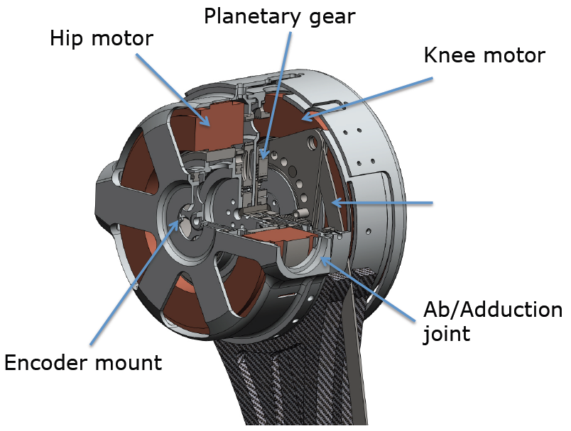
To verify the method, we implemented it on the MIT Cheetah. We constructed a custom set of motors using an off-the-shelf Emoteq HT-5001 three phase permanent magnet synchronous motor with a gap radius of 77.5 mm. A custom housing mounts it to the Cheetah and links it to the leg through a 5.8:1 planetary gear stage. Use of a single stage minimizes cascading loss from friction in multiple stages.
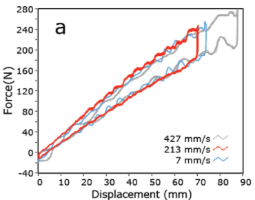
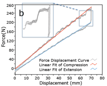
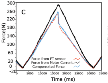
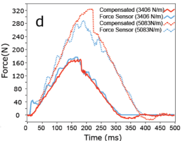
Experiments show that the actuator method does in fact allow for high force proprioceptive control of the Cheetah’s legs, as seen in the figures below.
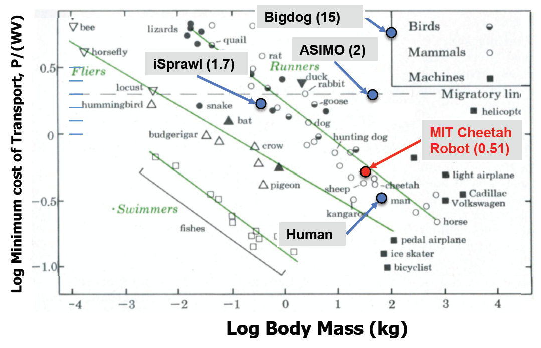
Even more, our design method yields a highly efficient actuator. The MIT Cheetah has a cost of transport of 0.51, far better than similar robots, and approximately the same as other running animals including its namesake.
Further Work
We’re working to develop a design tool to simplify the use of our method by others. We’re also completing our method by developing a comprehensive model of gear friction, especially its directionality, to improve our gearbox selections.
In the implementation, we are constructing new Cheetah actuators with better components, to increase the torque density and make a higher performance second generation Cheetah.
We’re also developing actuators with similar characteristics for smaller scales and applications in which a large gap radius motor cannot be used.