ARCHIVED PROJECTS
Dynamic Locomotion for the MIT Cheetah 2
Tail Design for Maneuverability
Dynamic Locomotion for the MIT Cheetah 2
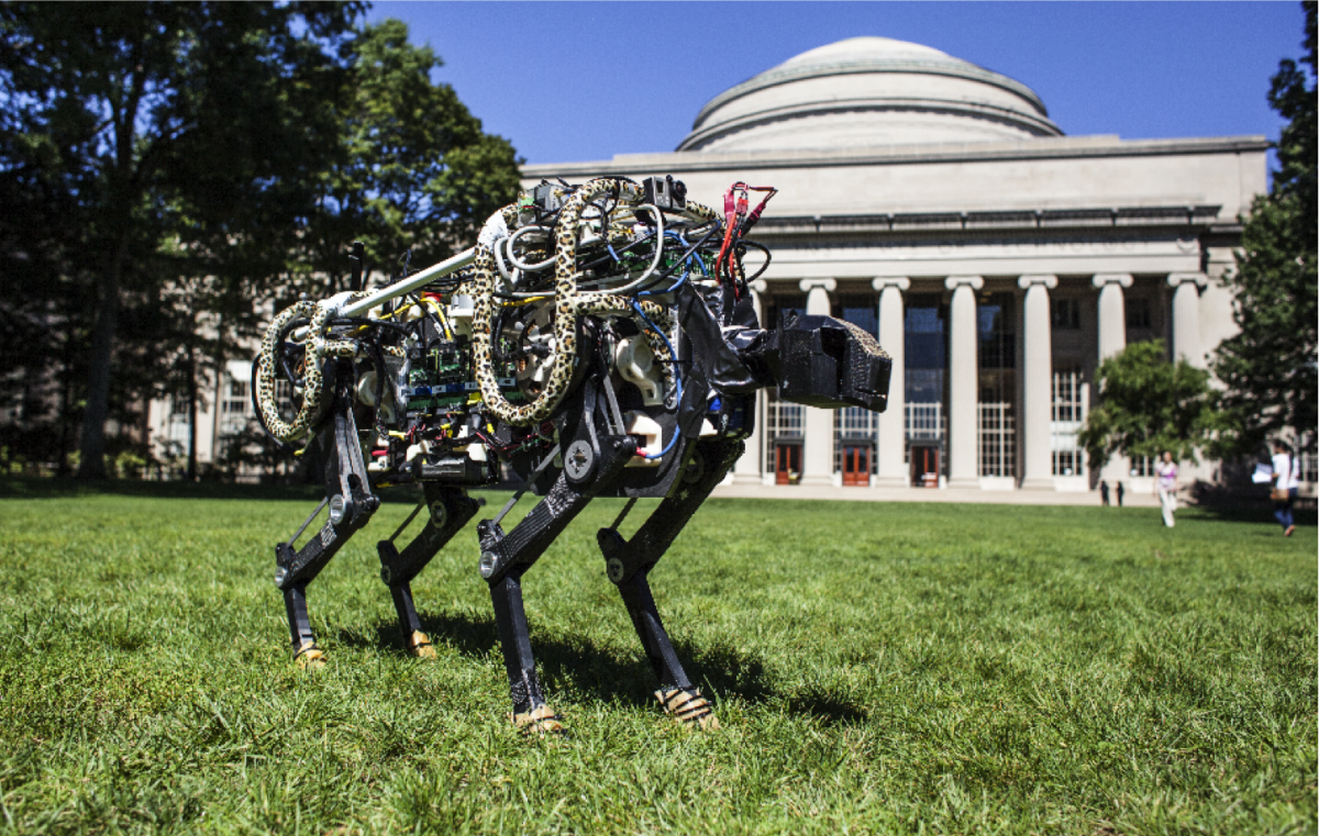
The MIT Cheetah II is a unique research platform that enables the study of dynamic locomotion capabilites in an experimental robot. Previous work on the MIT Cheetah I robot and optimal actuator design have come together to enable efficient running in this new machine at speeds from 0-6.4 m/s. Extensions to the running controller have enabled the robot to execute mild running turns and to autonomously jump of obstacles. The video below showcases many of the recently developed capabilites of the Cheetah II.
High-Speed Running Control Through Impulse Scaling
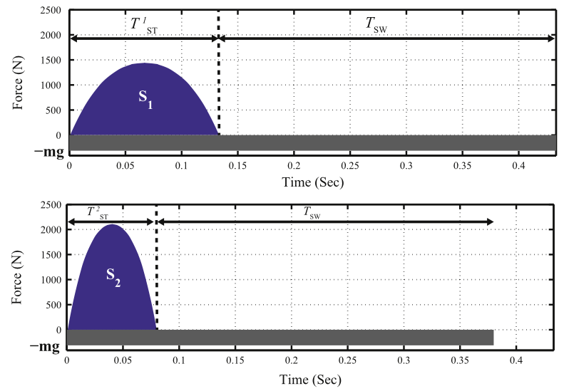
Control of high-speed running uses a fundamental concept of momentum balance as a guiding principle to shape the propreties of the gait across speeds. As shown in the figure below, the Cheetah pushses off the ground harder in shorter periods of stance, in order to balance the vertical impulse delivered through gravity over the stride. Additional feedback control is layered on top of these force profiles to balance the robot as it runs. The focus on these fundamental principles, realized through high-performance force-control, enables the Cheetah to run both in the laboratory and across rougher terrain outside.
Autonomous Jumping
More recently, the cheetah has demonstrated the capability to autonomously detect and jump over obstacles as it runs. The Cheetah can jump over obstacles up to 40cm in height (80% of leg length) while running at 2.5 m/s. The cheetah is able to take advantage of its speed and momentum to dynamically clear terrain obstacles that are well beyond the capabilites of previous legged machines that moved more statically. The video below describes some of the main algorithms that have been used to acheive this feat.
Publications
Park, H-W., and S. Kim, "Quadrupedal galloping control for a wide range of speed via vertical impulse scaling", Bioinspiration & Biomimetics, vol. 10, issue 2, pp. 025003, 2015.
Park, H-W., P. M. Wensing, and S. Kim, "Online Planning for Autonomous Running Jumps Over Obstacles in High-Speed Quadrupeds", Robotics: Science and Systems, 2015.
Park, H-W., SI. Park, and S. Kim, "Variable-speed quadrupedal bounding using impulse planning: Untethered high-speed 3D Running of MIT Cheetah 2", Robotics and Automation (ICRA), 2015 IEEE International Conference on, May, 2015.
Park, H-W., M. Yee Chuah, and S. Kim, "Quadruped bounding control with variable duty cycle via vertical impulse scaling", IEEE/RSJ International Conference on Intelligent Robots and Systems (IROS 2014), Sept, 2014.
MIT HERMES Project
The nuclear reactor meltdown the Fukushima Daiichi Power Plant in March 2011 is considered to be the greatest nuclear disaster since Chernobyl. It is estimated that if the cooling system could have been turned back on within a few hours of the initial failure, then the catastrophe could have been greatly minimized. Imagine if a human could have entered the facility after the disaster and performed the required task. This wasn’t an option because any human would be harmed by the high level of radiation before even getting near the Power Plant. So, what if we could send a human-like machine immune to radiation and able to perform activities similar to a human? This intuitive idea is the core concept of HERMES (Highly Efficient Robotic Mechanisms and Electromechanical System) at the Biomimetic Robotics Laboratory at MIT.
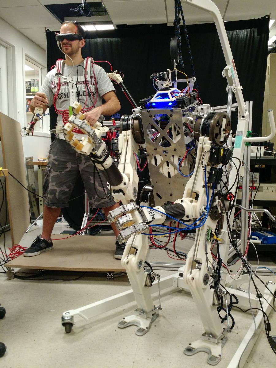
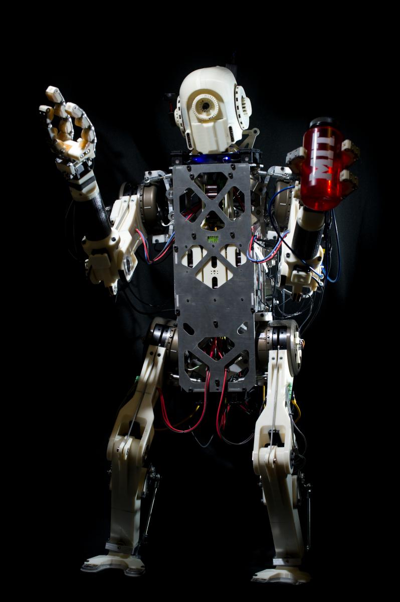
This work includes the concept, design, and experimental implementation of a full-body teleoperation system for human-in-the-loop control of a humanoid robot. The purpose of this Human-Machine Interface (HMI) is to create a new media to aid the task of bilateral feedback during full-body teleoperation of humanoid robots. It explores human’s primitive motor skills to enhance the dynamic behavior of the slave platform to a performance level comparable to humans. This project aims to leverage legged robot’s performance to respond to disaster situations such as nuclear, fire, or chemical hazards. We expect to reliably deploy a legged platform to a dangerous environments and perform powerful manipulation tasks such as hammering/axing, moving/lifting heavy objects, etc. We believe this is the key technology that allows for the paradigm shift from quasi-static regime to truly dynamic performance of humanoid robots.
HERMES at MIT News:
HERMES Team entry at UAE Robotics for Good Award:
For the past two years, we have been working on the first version of the HERMES System, including the Human Machine Interface (Balance Feedback Interface and Motion Capture Suit) and the humanoid robot itself. All the hardware and software is developed and tested in the lab so the team can easily modify and improve the machine in the hardware and software level.
Publications
J. Ramos, A. Wang, and S. Kim, "Robot-Human Balance State Transfer during Full-Body Humanoid Teleoperation Using Divergent Component of Motion Dynamics", Robotics and Automation (ICRA)>, 2016 IEEE International Conference on. IEEE, 2016. (Accepted)
J. Ramos, A. Wang, J. Mayo, W. Ubellacker, and S. Kim, "A Balance Feedback Interface for Whole-Body Teleoperation of a Humanoid Robot and Implementation in the Hermes System", Humanoid Robots, 2015 15th IEEE-RAS International Conference on. IEEE, 2015.
A. Wang, J. Ramos, J. Mayo, W. Ubellacker, and S. Kim, "The HERMES Humanoid System: A Platform for Full-body Teleoperation with Balance Feedback", Humanoid Robots, 2015 15th IEEE-RAS International Conference on. IEEE, 2015.
J. Ramos, A. Wang, and S. Kim, "A Balance Feedback Human Machine Interface for Humanoid Teleoperation in Dynamic Tasks", Intelligent Robots and Systems (IROS), 2015 IEEE/RSJ International Conference on., IEEE, 2015.
Tail Design for Maneuverability
Motivation
The Biomimetic Robotics Lab investigates the way of using a tail to improve maneuverability of the MIT Cheetah. The research was initiated with the inspiration from videos, showing that the cheetah’s turn is accompanied by a movement of its tail, and some researches in biology, describing that cats or dogs are moving their tail during locomotion. We end up with hypothesizing that a tail may enhance balance of the legged robot. This hypothesis is investigated with three examples.
External disturbance rejection using a tail
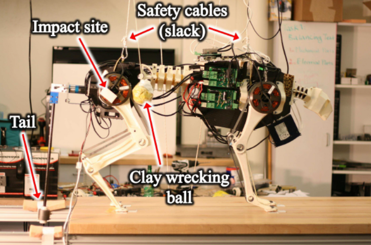
A robotic tail is designed and implemented on the MIT Cheetah to verify its effect on balance when external disturbance exist. The mass of the tail is 0.74 kg and the moment of inertia about the motor rotation axis is 0.160 kg m^2. The figure below depicts the experimental setup; the MIT cheetah is set to stand while the clay wrecking ball is swung into the impact site on the rear pelvis.
The video below shows that a large disturbance, which is enough to fell down the MIT Cheetah, is applied and the tail effectively stabilizes the body after the disturbance.
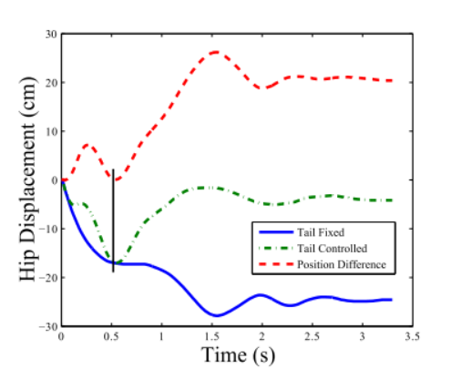
The plot below compares the horizontal position of the hip with/ without tail actuation. Green dash-dotted line indicates the horizontal position of the hips with the activated tail, while Blue solid line indicates that with the tail held fixed. Red dotted line represents the difference between two lines.
Comparison of a reaction wheel and a tail
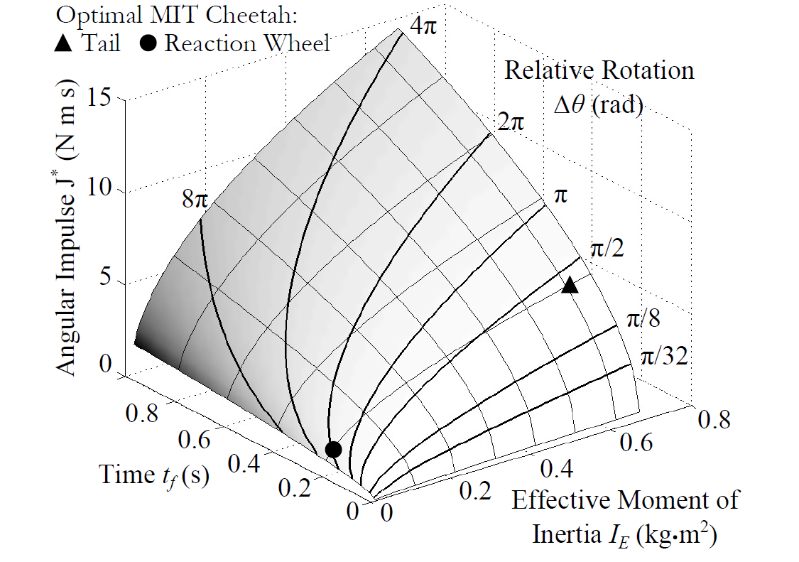
A reaction wheel, a well known engineering technology, and a tail are compared, in terms of their effectiveness of reorienting the body in cases when space, power, and time are limited. A reaction wheel is designed to fit within a volume so that it can rotate continuously, whereas a tail is allowed to have greater dimensions and greater effective moment of inertia, but it cannot rotate continuously without collision. Given different geometric constraints and with the assumption that either tool is operated while cheetah is in the air, maximum impulse, or average torque, is computed for each, within a time of interest. The figure below shows that a tail is appropriate when space is available for a high moment of inertia and the time of interest is very short.
Attitude Maneuvers using a tail
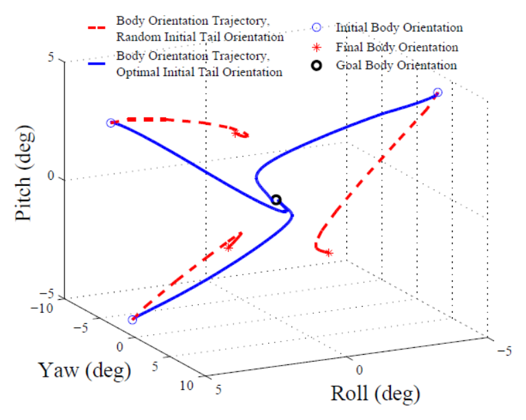
We proposed a simple feedback controller for three-axis spatial maneuvers using a straight, narrow tail to provide reaction moments. Control law is designed and followed by optimization to reorient the body from arbitrary orientation to a desired one (zero roll, pitch and yaw). At each instant, the controller finds the orientation and angular velocity of the body, computes the desired axis of rotation and angular momentum difference to achieve a desired orientation. Desired torque is calculated and projected onto the space of achievable torques. If it is allowed to optimize the initial tail orientation as if it was a planned maneuver, the performance becomes much better. The figure below shows that the controller successfully achieves a desired landing orientation during a limited flight time in simulation.
Further goal
The advantage and usefulness of tail in case of mid-air usage with single operation is well shown in the above results. More careful strategy is required to operate a tail continuously, considering characteristics of legged robots. To address this issue, one of ideas we have is that tail can be used as to help legs by 'earning short time' in between leg sequence so that a body stays in the stable region when a correcting foot placement can be made. The idea is being verified via simulation with more detailed model.
Publications
Briggs, R., J. Lee, M. Haberland, and S. Kim, "Tails in Biomimetic Design: Analysis, Simulation, and Experiment", IEEE/RSJ International Conference on Intelligent Robots and Systems, Vilamoura, Portugal, IEEE, 11/2012.
Swing Leg Retraction
Swing leg retraction (SLR) is a behavior exhibited by humans and animals in which the airborne front leg rotates rearward prior to touchdown. It is hypothesized that SLR enhances running performance of biological systems, and that we might use SLR to improve the performance of legged robots. To test these hypotheses, the Biomimetic Robotics Lab investigates the effects of swing leg retraction on several metrics of running performance,
- Small disturbance stability and large disturbance rejection
- Touchdown energy losses and overall energetic efficiency
- Potential for injury, as measured by leg forces
- Footing stability, as measured by foot slip distance and horizontal forces
using several models of varying complexity,
- Spring Loaded Inverted Pendulum (SLIP)
- Biped with massive, telescoping legs
- Biped with massive, telescoping legs and torso
- Biped with massive, kneed legs
and with two methods,
- Simulate the effects of a given control law for which swing leg retraction rate can be independently varied to measure running performance
- Optimize periodic trajectories (limit cycles) that maximize a measure of running performance for each of a range of swing leg retraction rates
We use the results of these studies to develop intuition for robot controller design.
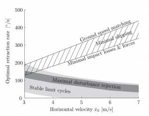
According to a modified SLIP model, the optimal retraction rate for minimal impact losses (and presumably higher overall energetic efficiency) is generally higher than the optimal retraction rate for maximum stability and disturbance rejection. Moreover, this tradeoff between energetic efficiency and stability becomes increasingly severe as running speed increases.
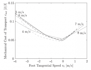
For simple telescopic-legged robots, increasing swing leg retraction rate (increasing foot tangential speed) results in improved energetic efficiency (lower mechanical cost of transport) up to a point. More specifically, for a range of running speeds, the swing leg retraction rate which minimizes mechanical cost of transport is that required to zero the foot tangential speed (that is, the component of the absolute velocity of the foot at touchdown in the direction perpendicular to the axis of the leg).
Publications
Karssen, J. G. D., M. Haberland, M. Wisse, and S. Kim, "The effects of swing-leg retraction on running performance: analysis, simulation, and experiment", Robotica, vol. 33, issue 10, pp. 2137-2155, December 2015.
Karssen, J. G. D., M. Haberland, M. Wisse, and S. Kim, "The optimal swing-leg retraction rate for running", Robotics and Automation (ICRA), 2011 IEEE International Conference on, Shanghai, China, IEEE, 05/2011.
Haberland, M., J. G. D. Karssen, S. Kim, and M. Wisse, "The effect of swing leg retraction on running energy efficiency", Intelligent Robots and Systems (IROS), 2011 IEEE/RSJ International Conference on, San Francisco, CA, IEEE, 09/2011.
Biotensegrity
Leg’s musculoskeletal system with an adaptive neuromuscular control employs a synergistic arrangement of bones, muscles, tendons and ligaments to withstand the high ground reaction forces in a relatively light structure. For example consider the anatomical arrangement of the human leg. (See Fig.1) When there is a large load at the metatarso-phalangeal jointsfootnote (ball of the foot) during running, the ankle (if foot is considered as rigid body as shown in Fig.1c ) would experience a high moment (roughly 309 N.m for a 70 kg human. Assuming the length between the ball of the foot and ankle is around 0.15m and the maximum ground reaction force is three times of weight. However, the ground reaction force is distributed through the bones, tendons and muscles. As a results plantar fascia, the Achilles tendon and the gastrocnemius muscle carry tension and the bones including Metatarsus bones and tibia are loaded mainly in compression. As the bones have better strength at compression than tension and tendons and muscles have high strength in tension this distribution of the loads provide a design which is strong and light. The tendon also plays an important role in providing necessary compliance and energy storage. The same principle seen in humans (plantigrades) can be seen in unglulates (Nail runners as horse, Fig1.b and digitigrades (e.g. cats and dogs).
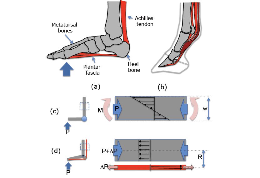
In high speed legged robots, while the legs need to withstand ground reaction forces substantially higher than the robot’s weight, minimizing the leg inertia is highly desirable for high speed locomotion. To achieve high speeds, it is essential to obtain high stride frequencies. High stride frequencies require a very short leg protraction time while in the flight phase. In legged robots, high stride frequency can be made possible in two ways, 1) increasing the actuator capacity, and 2) decreasing the leg inertia. The current state of the art in actuator technology precludes increase in actuator capacity without considerably increasing the overall weight. Hence, decreasing the total inertia of the leg structure is more desirable.
Reducing the mass of the legs is the key technique to reduce the leg inertia. However while decreasing the mass, the structural integrity should be maintained, as the legs must withstand high ground impact forces. Therefore designing a high speed legged robot imposes a serious tradeoff between agility (which requires low inertia) and strength of the leg design (which requires bulky structures). This trade off becomes even more critical in distal part of the leg since it contains more complex articulated features. These features are necessary for providing more functions including smooth collision to the ground, elastic energy storage, and added control.
Most current mechanical designs for legged robots deal with this trade-off by using strong and bulky legs made of high strength to weight ratio materials such as Titanium and Aluminum. In addition, it is well known that compliance in leg structures is of high importance in energy efficient running. Using metals lead to very stiff legs making it necessary to introduce other strategies to introduce leg compliance. An alternative way can be adopting the biomimetic solutions found in nature and using available engineering knowledge to provide a feasible engineered solution.
Some of the characteristics of biological systems such as distributing the load, energy storage, using tensile forces having high strength while being light remind us of some pin-jointed structures such as trusses, Tensegrities and cable structures well known in Engineering. Extraction of such design principles and taking advantage of a synergistic arrangement of bones and tendons has several potential benefits: 1) It allows the legged robot designers to use cheaper materials for the leg structures which are also easier and faster to fabricate (e.g. molding plastics), 2) it decreases the weight of the leg structure and thereby reduces the total inertia which has serious implications in energy efficient running, and 3) It contains the elements that can be used as series elastic to provide compliance and energy storage.
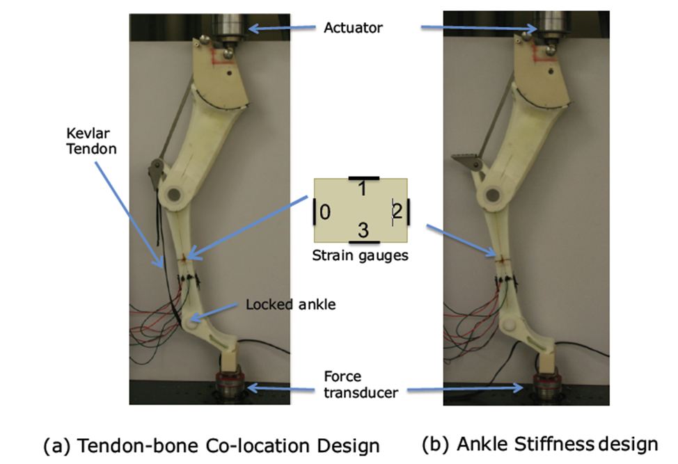
The complexity of the foot structure with its neuromuscular control, however, cannot be resembled easily by available engineering material and knowledge. In order to have a feasible passive leg design some of the concepts noticed in the biomechanics of the leg are adopted and a simplified but feasible design based on the available techniques in Engineering is proposed (Fig.2 and Fig.3). Specifically, two methods for decreasing the weight and inertia of the mobile robot’s legs are tried. First, a bio-inspired leg with tendon is devised (See Fig.2). Second, a new bio-inspired foam-core prototyping method for quick and light fabrication of the leg was implemented to make a lighter leg (See Fig.3).

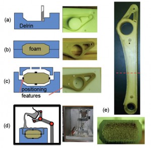
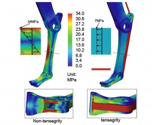
To evaluate the potential performance of the new leg design, static finite element analysis for a specific loading configuration was performed. The results of the finite element analysis for the two design concepts (without and with tendon) are shown in Figure 4. In the tendon- design, the stresses in the radius are much lower and in pure compression at the same location due to the tendon receiving tension force compensating the bending.
The experimental results of stresses for the same loading configuration on the actual leg were also measured and confirmed the FEM results. (Fig. 5)
Publications
Ananthanarayanan, A., M. Azadi, and S. Kim, "Towards a bio-inspired leg design for high-speed running", Bioinspiration & Biomimetics, vol. 7, issue 4, 08/2012.